Mechanical design
The BallCuber : 4x4x4 Rubik's Cube solving machine
The mechanical design is the most complicated part of this project.
Introduction
The spirit of this was to be able to solve the cube as fast as possible. Knowing that the mechanical design had to be thought this way. That means we had to think about a solution that needs less steps to solve and be able to do these steps fast.
We decided to put one actuator on each row of the cube except one on each direction (explained on this page). That means (4-1)rows * 3 axes = 9 actuators.
Kinematic
Let’s dive into the current kinematic of the Ballcuber.
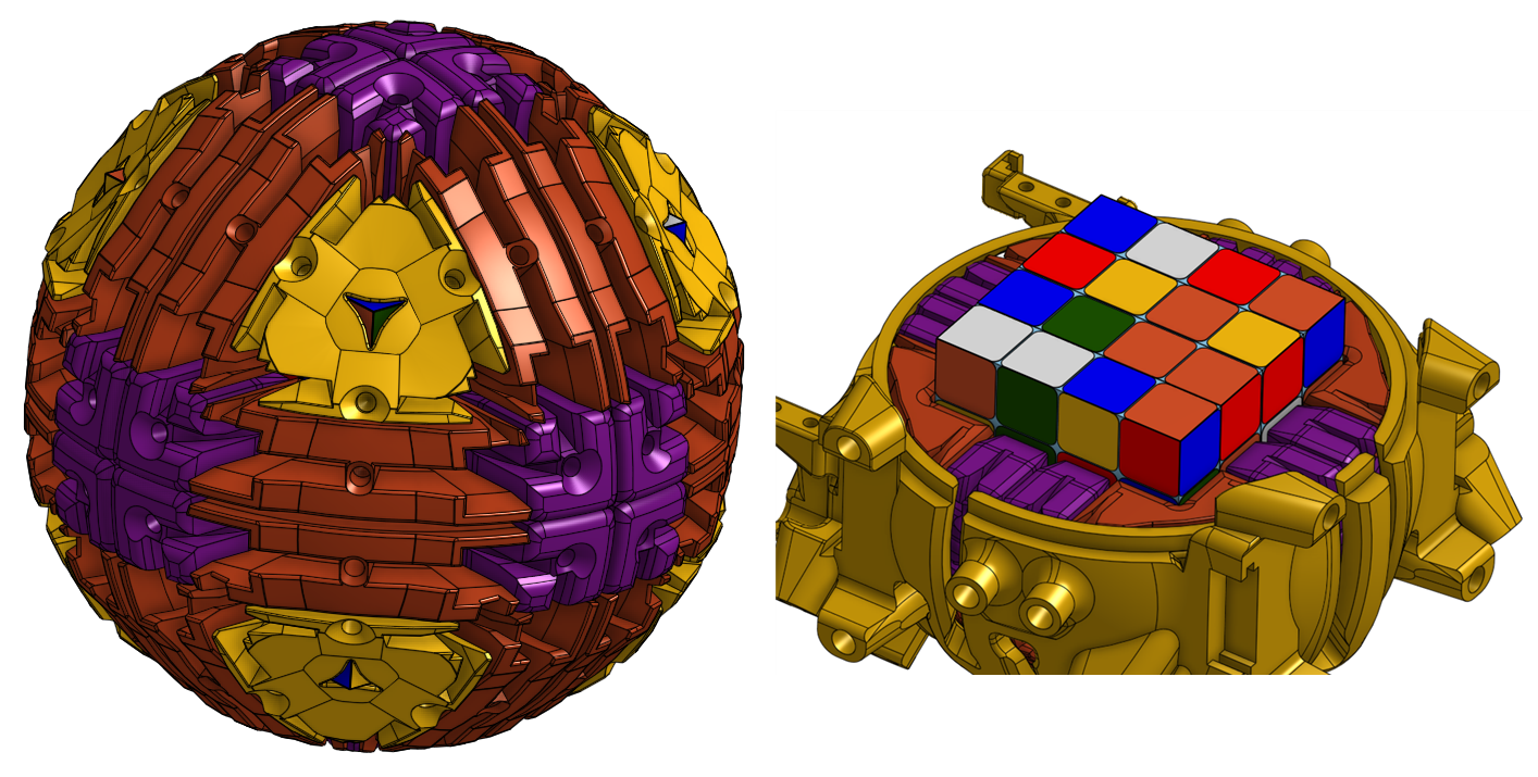
Holding the cube
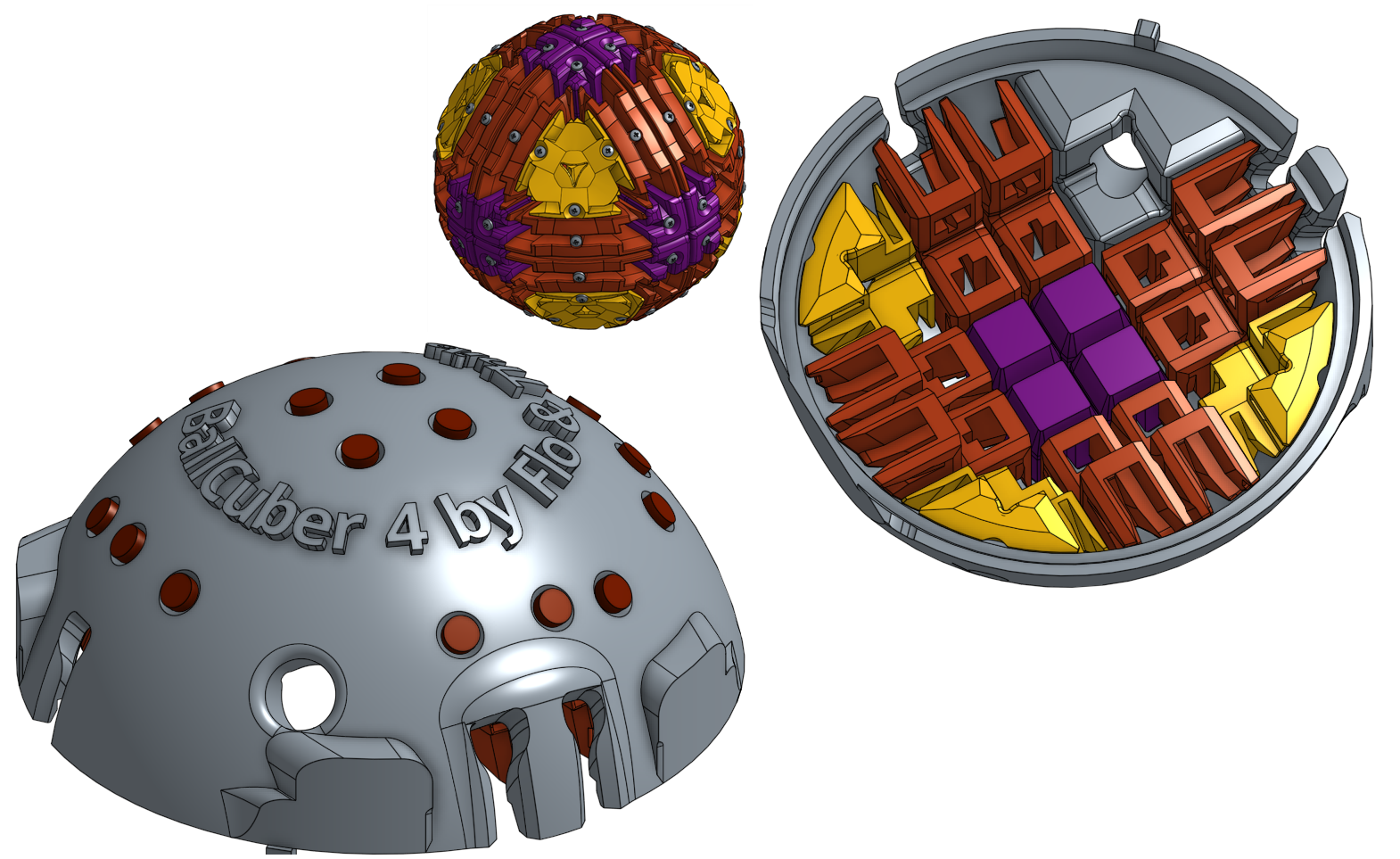
The cube is hided inside the Ballcuber. The yellow outer frame has an inner spherical surface where 3 types of parts can slide. Those 3 types of part hold the cube at the center and contribute to “build” a pivot mate between each row of the cube and the spherical surface. On the following images the highlighted surfaces are the one that slide on the inner spherical surface of the outer frame.
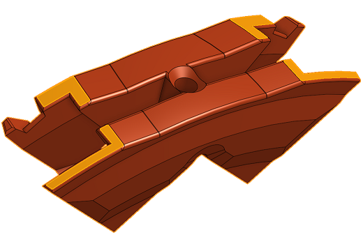
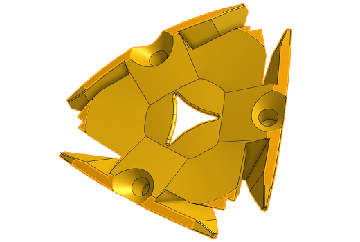
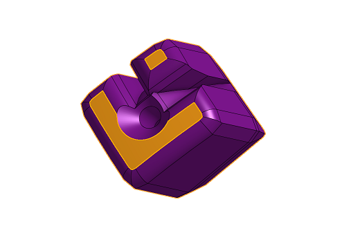
Those parts are all around the cube and it looks like this with the cube and the surrounding parts without the frame. We can see the cube’s corners in the middle of the yellow “Corner”. On the right we can see the cube inside the frame held by the surrounding parts:
This sphere can slide inside the frame which is this yellow part as shown above :
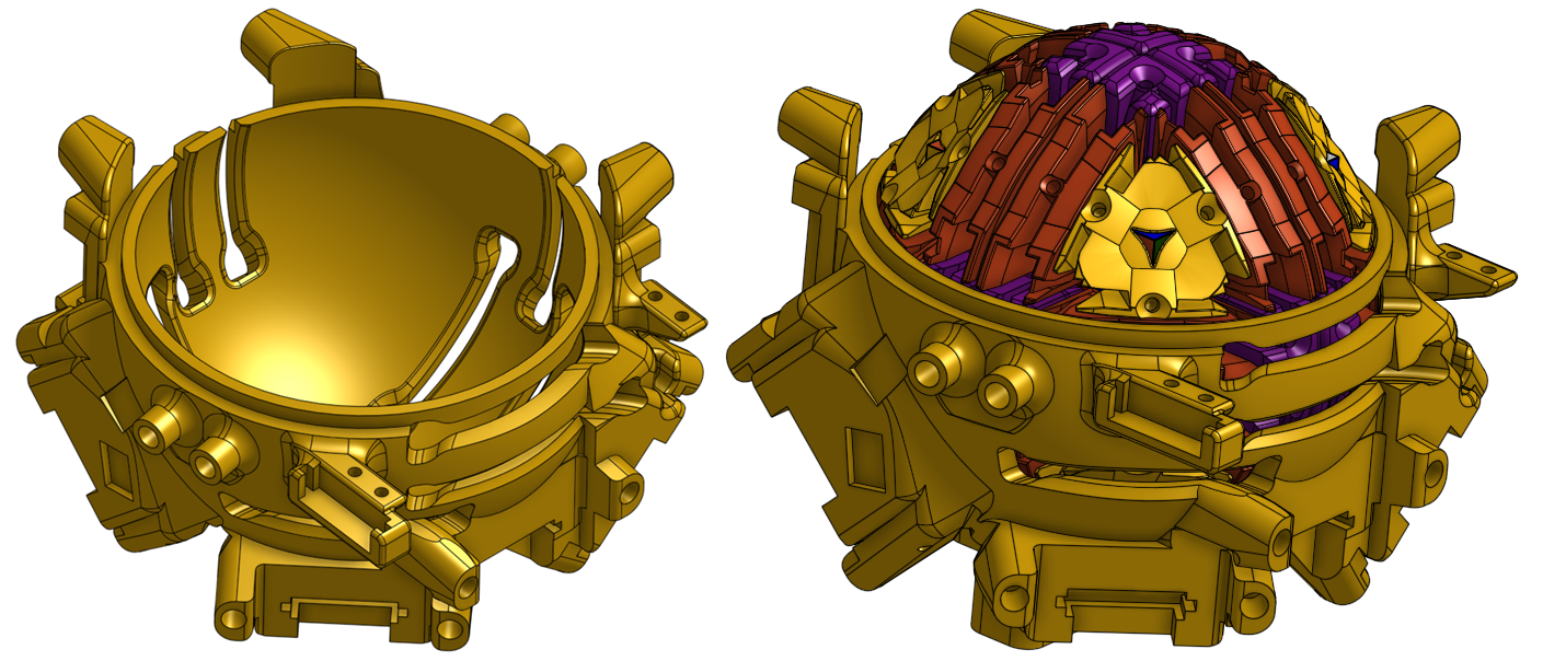
All the parts presented in the previous pictures have been 3D printed.
Rotating a cube’s row
The rotation of a cube’s row is done with a mechanism inspired by the Geneva drive.
Here is a quick Gif of the current Geneva drive inspired mechanism with a cross section to see the cube’s row intermittently rotating.
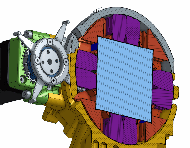
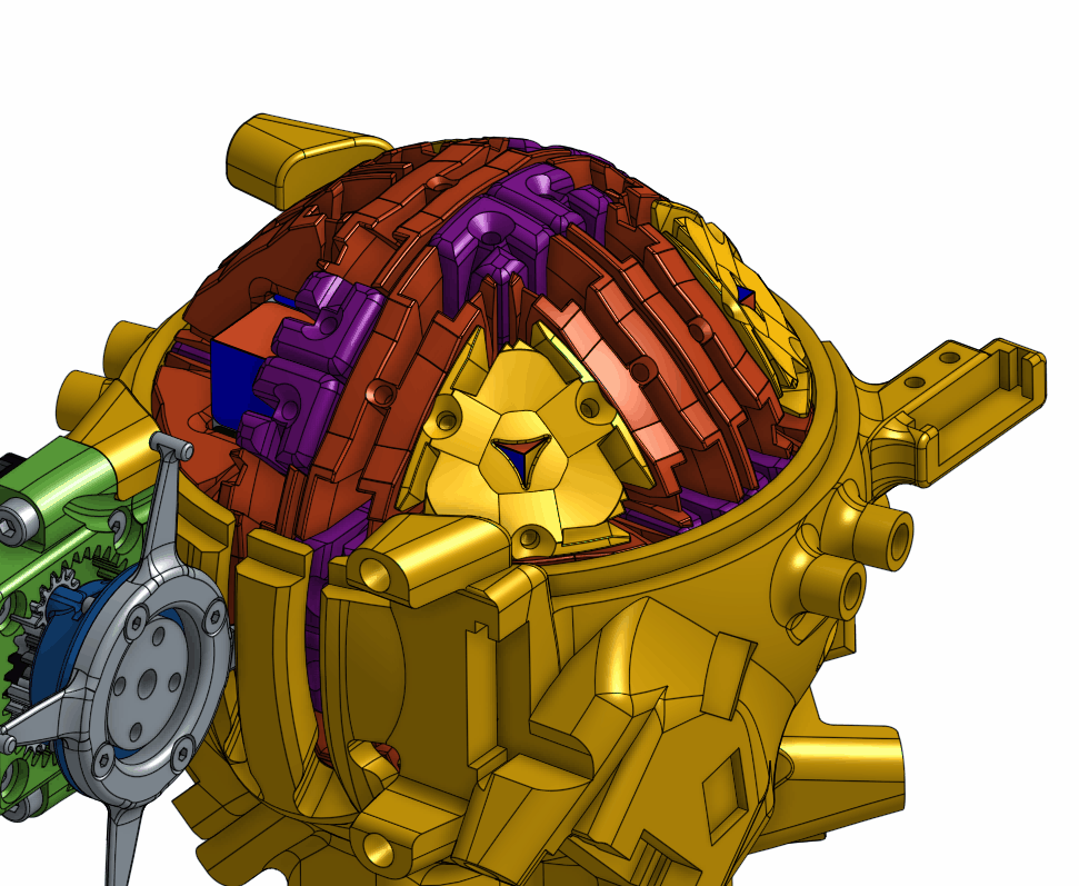
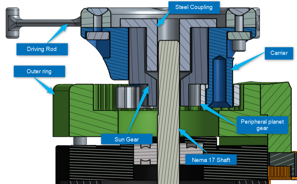
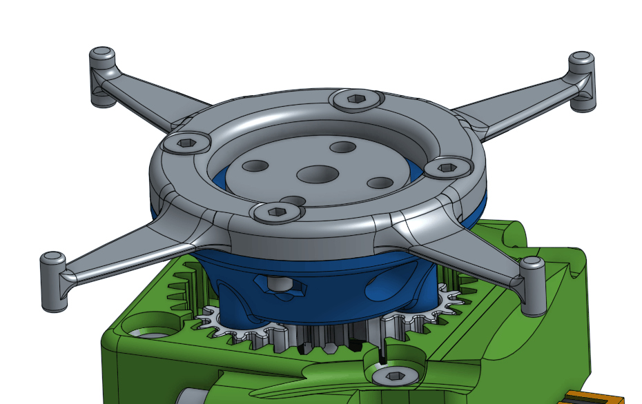
On the previous GIF we can see that the stepper drives an epicyclic gear that, at the end drives a driving rod (Rotation speed is a 1/4 of the stepper’s speed and so the available torque is 4 times what the stepper can give). This driving rod has a small pin at the tip of each branch. This pin goes into a slot and push one part that is between the frame and the cube. By pushing this part the cube’s row starts to rotate around its center. The driving rod has 4 branches so a 180° of the driving rod correspond to a 90° rotation of the cube’s row.
The kinematic we designed lets us move perpendicular rows one after another as we can see there :
Motors
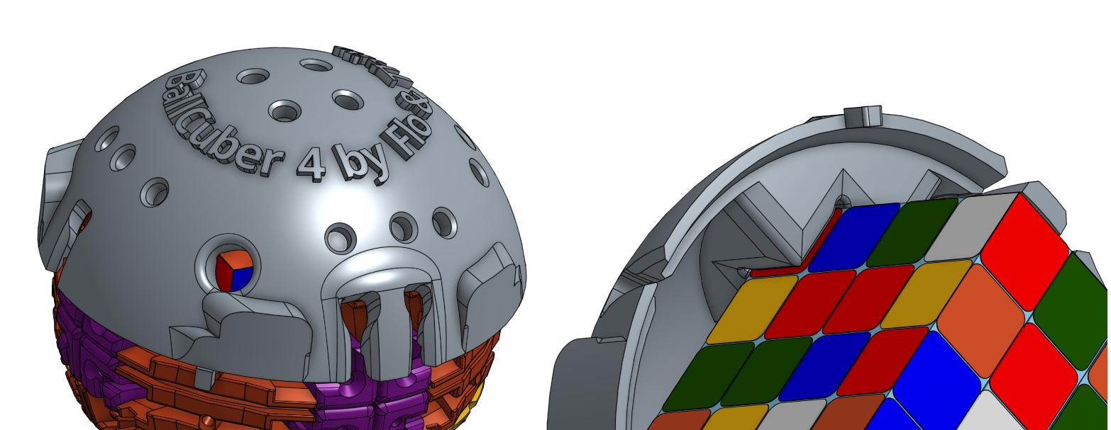
We decided to work on the Revenge Cube which has 4 rows on each direction. To be as fast as possible we need to control the rotation of each rows directly. This would have meant 4 rows * 3 directions = 12 motors. That’s quite a lot and not necessary as we can lock one corner of the cube which means not moving the 3 rows containing this corner. In this case, if the resolution algorithm tells us to move the locked row we just need to rotate the 3 other rows in the opposite direction. The resulting movement is not the same but the resulting cube’s arrangement is the same. That’s the reason why we have 3 rows * 3 directions = 9 motors on the Ballcuber. In the following picture, we can see the locked corner which is visible from the outside of the Ballcuber. This locked corner is located on the hood.
Other features
Magnets on the hood
The Ballcuber has 24 + 24 + 7 = 55 parts between the cube and the frame and we need to be able to easily reach the cube. The frame is the part with all the motors and the hood is the part we remove to reach the cube. We’ve added magnets on the hood and ferromagnetic parts (simple screws) on the inside parts so that when we remove the hood all the parts that are in the hood stay in it. This is shown in the following picture :
Interchangeable motors and embedded 7 pin connector
The motors are connected to the ballcuber using a 7 pin connector. This allows mounting/dismounting of the motors for tunning needs.
3D printed epicyclic gear
As the Nema 17 motors don’t have enough torque, we’ve added an epicyclic gear to increase the available torque and as a consequence lower the speed. Below is a cross section of the epicyclic gearing train.
Threaded inserts for plastic
Assembling 3D printed parts has been done using threaded inserts. Those inserts have been pushed in using a soldering iron to heat the insert and melt the plastic around it.
OnShape
All parts has been designed with OnShape.
You can have a look on the CAD model here :
![]()
Onshape is a CAD software with powerful collaboration tools and real-time analytics. It is both a desktop and mobile app.